What is a Power Line EMI Filter? |
A power line EMI Filter is a primary tool available to the designer of electronic equipment to control conducted EMI / RFI both into the equipment
(potential equipment malfuncion) and out of the equipment (potential interference to other system elements or RF communication). By controlling the EMI / RFI conducted onto the power
line, a power line EMI Filter also contributes significantly to the control of radiated EMI / RFI.
EMI Filters can also be thought of as "impedance mismatching networks" at higher frequencies in the attenuation band.
Network analysis shows that, the greater the mismatch of filter impedance to terminating impedance, the more effective the filter is in attenuating RF energies.
An EMI filter is a multiple-port network of passive components arranged as a dual low-pass filter: one network for common mode attenuation, another network for differential mode attenuation.
The network provides attenuation of RF energy in the stopband of the filter (typically above 10KHz), while passing the power current (50-60Hz.) with little or no attenuation.
|
How does an EMI Filter work? |
Maximum power transfer occurs when source and load impedance are matched. The EMI filter is an inductor-capacitor network that aims to cause MAXIMUM mistmatch between the impedances, and therefore reduces the amount of EMI power
to be transfered from the noise source onto the power lines.
The magnitude of this transfer characteristics describes the attenuation performance of the EMI filter. In the power line environment however, the source and load impedances are not defined. Therefore the industry has standardised upon
the practices of verifying the filter uniformity through measurement of attenuation with 50 ohm resistive source and load terminations. This measurement is defined to be the Insertion Loss(I.L) of the EMI Filter.
I.L = 10 log (PL(Ref)/PL
Where PL(Ref) is the power transfered from the source to the load without the EMI filter, and PL is the power transfered when an EMI filter is inserted between the source and load. The Insertion Loss may also be expressed in terms of voltage and current ratios as shown:
I.L = 10 log (VL(Ref)/VL)
I.L = 10 log (IL(Ref)/IL)
where Vl(Ref) and Il(Ref) are measured without EMI filter and VL and IL as measured with EMI Filter.
|
What are the components used in an EMI Filter? |
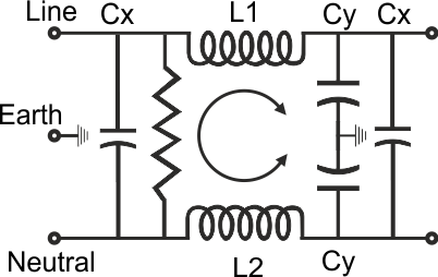
Above is a circuit diagram of a typical single phase power line EMI Filter. The inductors L1 and L2 are usually wound in a current compensated fashion, on a toroidal core.
This winding method allows flux due to differential mode currents and mains currents to cancel each other, while common mode currents will be added together. This gives a
large inductance to common mode currents and ensures that the inductor will not be saturated by the large magnetic flux produced by the mains current. We at EMITECH Micro Components, employ a
special winding technique to ensure that the inductors have very less interwinding stray capacitance, thereby significantly improving the high frequency attenuation of our filters.
The capacitors placed between the phases, known as Class 'X' capacitors must offer a high pulse voltage rating and are used to attenuate differential mode interference. The capacitors between
phase lines and earth, known as Class 'Y' capacitors must comply with more stringent rating and are used to attenuate common mode interference. The value of the Y capacitor is restricted by the
permissible leakage current allowed. The maximum leakage current is governed by standards and regulations and depends upon the type of equipment. We use safety approved and certified capacitors
in our EMI filters.
To achieve higher attenuation or an increase in the effective working frequency range, more complex filters circuits than shown above can be made using more common mode or differential mode inductors and capacitors.
|
How do you select a power line EMI Filter? |
The only way to select and qualify a power line EMI Filter is to test the unit in your equipment. As mentioned above, the performance is highly dependent on equipment load impedance. Filter performance cannot be derived from single impedance (50 ohm) insertion loss data.
Performance is a complex function of filter element impedances and equipment impedances which vary in magnitude and phase over the frequency spectrum of interest. EMI Filter selection testing should be performed in your equipment to your required level
of performance for both conducted emission control and susceptibility control.
|
|
How do you perform conducted emission tests?
Conducted emission testing requires a quiet RF environment - usually a shielded enclosure, a line impedance stabilisation network and an RF coltage measurement
instrument such as a tuned receiver or spectrum analyzer. The RF ambient of the test environment should be atleast 20dB below the desired compliance limit for accurate results.
The line impedance stabilisation network( LISN ) is required to establish a defined source impedance for the power line input. This is important part of the test procedure, since this impedance
directly affects the measured levels. The correct bandwidth for the measurement receiver is also a critical test parameter.
|
|
How do you perform susceptibility tests?
Susceptibility testing involves injection of noise onto the power input lines while monitoring the equipment for proper
operation.
|